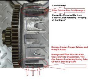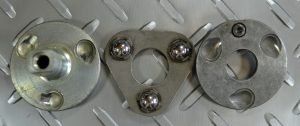
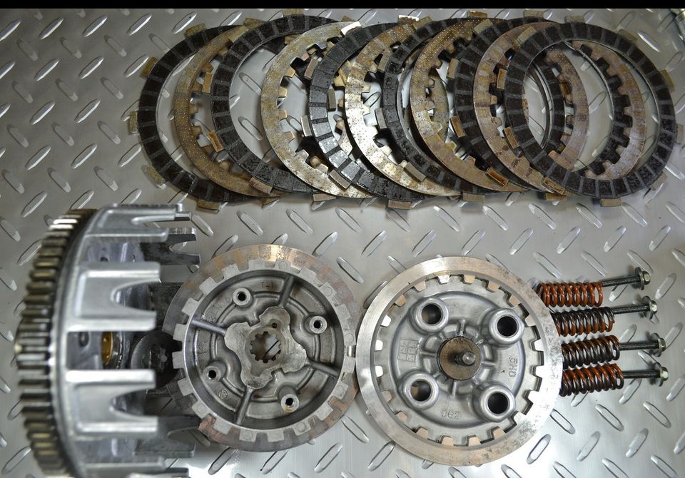
Alternating Layers of Fiber Friction Disc and Steel Clutch Plates Clamped Together By the Pressure Plate and Springs
This article will focus on the Action, the Why, and the How the different components of the Modern and Manual Motorcycle Clutch come together to make these mechanical assemblies work. The reference to Modern is relative because the earliest motorcycle clutches were little more than a lever and roller that removed or added slack to the leather belt that connected the engine and rear wheel. The reference to Manual is needed because some smaller bikes and ATV’s use Automatic Clutches that work through increasing RPM and centrifugal forces that move outward to engage 2 friction surfaces to couple the engine and transmission.
In their natural, at-rest state, the alternating layers of fiber Friction Plates (crankshaft driven) and metal Clutch Plates (transmission input) are tightly clamped and stuck together. An outer hub/Basket (crankshaft driven) is used to maintain the Friction Disc while an inner hub/Boss is used to maintain the metal Cutch Plates that drive the transmission input shaft. The alternating sandwich of fiber disc and metal plates is clamped tightly (stuck together) by the Pressure Plate and Pressure Plate Springs. This sandwich stays tightly clamped until the Clutch Lever is pulled.